Thursday, December 15, 2011
ELECTRICAL or ELECTRONIC COMPUTERS
EDVAC :- It was invented in 1947 A.D. by
John Von Neuman.
EDSAC :- It was invented in 1941 A.D. by
Prof. M.V. Wilkes.
UNIVAC – I :- It was invented in 1951 A.D. by Univac.
ELECTRO - MECHANICAL CALCULATING DEVICE
Mark - I :- It was invented in 1943 A.D. by Howard Aiken.
ABC :- It was invented in 1942 A.D. by Dr. John Atnasoff.
ENIAC :- It was invented in 1946 Dr. John W.. Mauchly &
J. Presper Eckert.
MECHANICAL CALCULATING DEVICE
Abacus :- It was invented in 3000 B.C. It was used
for calculating.
Napier’s Bone :- It was invented in 1614 A.D. by
John Napier.
Pascaline :- It was invented in 1642 A.D. by
Blaise Pascal.
Stepped Recknor :- It was invented in 1671 A.D. by
Gott Fried Wilhelm von Leibniz.
Jackquard’s Loom :- It was invented in 1802 A.D. by
Joseph Marie Jackquard.
Difference Engine :- It was invented in 1822 A.D. by
Charles Babbage.
Analytical Engine :- It was invented in 1833 A.D. by
Charles Babbage.
Hollarith’s Tabulator :- It was invented in 1877 A.D. by
Hollarith’s Tabulator.
Wednesday, June 15, 2011
RDBMS
A relational database management system (RDBMS) is a database management system (DBMS) that is based on the relational model as introduced by E. F. Codd. Most popular commercial and open source databases currently in use are based on the relational database model.
A short definition of an RDBMS is: a DBMS in which data is stored in tables and the relationships among the data are also stored in tables. The data can be accessed or reassembled in many different ways without having to change the table forms.
A short definition of an RDBMS is: a DBMS in which data is stored in tables and the relationships among the data are also stored in tables. The data can be accessed or reassembled in many different ways without having to change the table forms.
DBMS
A Database Management System (DBMS) is a software package with computer programs that control the creation, maintenance, and the use of a database. It allows organizations to conveniently develop databases for various applications by database administrators (DBAs) and other specialists. A database is an integrated collection of data records, files, and other database objects needed by an application. A DBMS allows different user application programs to concurrently access the same database. DBMSs may use a variety of database models, such as the relational model or object model, to conveniently describe and support applications. It typically supports query languages, which are in fact high-level programming languages, dedicated database languages that considerably simplify writing database application programs. Database languages also simplify the database organization as well as retrieving and presenting information from it. A DBMS provides facilities for controlling data access, enforcing data integrity, managing concurrency control, recovering the database after failures and restoring it from backup files, as well as maintaining database security.
Monday, June 13, 2011
QBASIC (Quick BASIC)
QBasic is an IDE and interpreter for a variant of the BASIC programming language which is based on QuickBASIC. Code entered into the IDE is compiled to an intermediate form, and this intermediate form is immediately interpreted on demand within the IDE .It can run under nearly all versions of DOS and Windows, or through DOSBox/DOSEMU, on Linux and FreeBSD.For its time, QBasic provided a state-of-the-art IDE, including a debugger with features such as on-the-fly expression evaluation and code modification.
Like QuickBASIC, but unlike earlier versions of Microsoft BASIC, QBasic is a structured programming language, supporting constructs such as subroutines and while loops.Line numbers, a concept often associated with BASIC, are supported for compatibility, but are not considered good form, having been replaced by descriptive line labels. QBasic has limited support for user-defined data types (structures), and several primitive types used to contain strings of text or numeric data.
Like QuickBASIC, but unlike earlier versions of Microsoft BASIC, QBasic is a structured programming language, supporting constructs such as subroutines and while loops.Line numbers, a concept often associated with BASIC, are supported for compatibility, but are not considered good form, having been replaced by descriptive line labels. QBasic has limited support for user-defined data types (structures), and several primitive types used to contain strings of text or numeric data.
Saturday, June 11, 2011
Program Design Language
Program Design Language (or PDL, for short) is a method for designing and documenting methods and procedures in software. It is related to pseudocode, but unlike pseudo code, it is written in plain language without any terms that could suggest the use of any programming language or library.
1.Pseudocode
Pseudocode is a compact and informal high-level description of a computer programming algorithm that uses the structural conventions of a programming language, but is intended for human reading rather than machine reading. Pseudocode typically omits details that are not essential for human understanding of the algorithm, such as variable declarations, system-specific code and subroutines. The programming language is augmented with natural language descriptions of the details, where convenient, or with compact mathematical notation. The purpose of using pseudocode is that it is easier for humans to understand than conventional programming language code, and that it is an efficient and environment-independent description of the key principles of an algorithm. It is commonly used in textbooks and scientific publications that are documenting various algorithms, and also in planning of computer program development, for sketching out the structure of the program before the actual coding takes place.
Aside from the basic four quadrant structure, decision tables vary widely in the way the condition alternatives and action entries are represented.Some decision tables use simple true/false values to represent the alternatives to a condition (akin to if-then-else), other tables may use numbered alternatives (akin to switch-case), and some tables even use fuzzy logic or probabilistic representations for condition alternatives.In a similar way, action entries can simply represent whether an action is to be performed (check the actions to perform), or in more advanced decision tables, the sequencing of actions to perform (number the actions to perform).
1.Pseudocode
Pseudocode is a compact and informal high-level description of a computer programming algorithm that uses the structural conventions of a programming language, but is intended for human reading rather than machine reading. Pseudocode typically omits details that are not essential for human understanding of the algorithm, such as variable declarations, system-specific code and subroutines. The programming language is augmented with natural language descriptions of the details, where convenient, or with compact mathematical notation. The purpose of using pseudocode is that it is easier for humans to understand than conventional programming language code, and that it is an efficient and environment-independent description of the key principles of an algorithm. It is commonly used in textbooks and scientific publications that are documenting various algorithms, and also in planning of computer program development, for sketching out the structure of the program before the actual coding takes place.
2.Flowchart
A flowchart is a type of diagram that represents an algorithm or process, showing the steps as boxes of various kinds, and their order by connecting these with arrows. This diagrammatic representation can give a step-by-step solution to a given problem. Process operations are represented in these boxes, and arrows connecting them represent flow of control. Data flows are not typically represented in a flowchart, in contrast with data flow diagrams; rather, they are implied by the sequencing of operations. Flowcharts are used in analyzing, designing, documenting or managing a process or program in various fields.
3.Decision table
Each decision corresponds to a variable, relation or predicate whose possible values are listed among the condition alternatives. Each action is a procedure or operation to perform, and the entries specify whether (or in what order) the action is to be performed for the set of condition alternatives the entry corresponds to. Many decision tables include in their condition alternatives the don't care symbol, a hyphen. Using don't cares can simplify decision tables, especially when a given condition has little influence on the actions to be performed. In some cases, entire conditions thought to be important initially are found to be irrelevant when none of the conditions influence which actions are performed.Aside from the basic four quadrant structure, decision tables vary widely in the way the condition alternatives and action entries are represented.Some decision tables use simple true/false values to represent the alternatives to a condition (akin to if-then-else), other tables may use numbered alternatives (akin to switch-case), and some tables even use fuzzy logic or probabilistic representations for condition alternatives.In a similar way, action entries can simply represent whether an action is to be performed (check the actions to perform), or in more advanced decision tables, the sequencing of actions to perform (number the actions to perform).
Friday, June 10, 2011
OSI model
The Open Systems Interconnection model (OSI model) was a product of the Open Systems Interconnection effort at the International Organization for Standardization. It is a way of sub-dividing a communications system into smaller parts called layers. Similar communication functions are grouped into logical layers. A layer provides services to its upper layer while receiving services from the layer below. On each layer, an instance provides service to the instances at the layer above and requests service from the layer below.
For example, a layer that provides error-free communications across a network provides the path needed by applications above it, while it calls the next lower layer to send and receive packets that make up the contents of that path. Two instances at one layer are connected by a horizontal connection on that layer.
Work on a layered model of network architecture was started and the International Organization for Standardization (ISO) began to develop its OSI framework architecture. OSI had two major components: an abstract model of networking, called the Basic Reference Model or seven-layer model, and a set of specific protocols.

To understand the function of the Physical Layer, contrast it with the functions of the Data Link Layer. Think of the Physical Layer as concerned primarily with the interaction of a single device with a medium, whereas the Data Link Layer is concerned more with the interactions of multiple devices (i.e., at least two) with a shared medium. Standards such as RS-232 do use physical wires to control access to the medium.
The major functions and services performed by the Physical Layer are:
The ITU-T G.hn standard, which provides high-speed local area networking over existing wires (power lines, phone lines and coaxial cables), includes a complete Data Link Layer which provides both error correction and flow control by means of a selective repeat Sliding Window Protocol.
Both WAN and LAN service arrange bits, from the Physical Layer, into logical sequences called frames. Not all Physical Layer bits necessarily go into frames, as some of these bits are purely intended for Physical Layer functions. For example, every fifth bit of the FDDI bit stream is not used by the Layer.
Careful analysis of the Network Layer indicated that the Network Layer could have at least three sublayers:
A number of layer management protocols, a function defined in the Management Annex, ISO 7498/4, belong to the Network Layer. These include routing protocols, multicast group management, Network Layer information and error, and Network Layer address assignment. It is the function of the payload that makes these belong to the Network Layer, not the protocol that carries them.
Although not developed under the OSI Reference Model and not strictly conforming to the OSI definition of the Transport Layer, typical examples of Layer 4 are the Transmission Control Protocol (TCP) and User Datagram Protocol (UDP).
Of the actual OSI protocols, there are five classes of connection-mode transport protocols ranging from class 0 (which is also known as TP0 and provides the least features) to class 4 (TP4, designed for less reliable networks, similar to the Internet). Class 0 contains no error recovery, and was designed for use on network layers that provide error-free connections. Class 4 is closest to TCP, although TCP contains functions, such as the graceful close, which OSI assigns to the Session Layer. Also, all OSI TP connection-mode protocol classes provide expedited data and preservation of record boundaries, both of which TCP is incapable.
This layer provides independence from data representation (e.g., encryption) by translating between application and network formats. The presentation layer transforms data into the form that the application accepts. This layer formats and encrypts data to be sent across a network. It is sometimes called the syntax layer.
The original presentation structure used the basic encoding rules of Abstract Syntax Notation One (ASN.1), with capabilities such as converting an EBCDIC-coded text file to an ASCII-coded file, or serialization of objects and other data structures from and to XML.
For More Detail Click In Sohil
For example, a layer that provides error-free communications across a network provides the path needed by applications above it, while it calls the next lower layer to send and receive packets that make up the contents of that path. Two instances at one layer are connected by a horizontal connection on that layer.
Work on a layered model of network architecture was started and the International Organization for Standardization (ISO) began to develop its OSI framework architecture. OSI had two major components: an abstract model of networking, called the Basic Reference Model or seven-layer model, and a set of specific protocols.

Layer 1: Physical Layer
The Physical Layer defines electrical and physical specifications for devices. In particular, it defines the relationship between a device and a transmission medium, such as a copper or optical cable. This includes the layout of pins, voltages, cable specifications, hubs, repeaters, network adapters, host bus adapters (HBA used in storage area networks) and more.To understand the function of the Physical Layer, contrast it with the functions of the Data Link Layer. Think of the Physical Layer as concerned primarily with the interaction of a single device with a medium, whereas the Data Link Layer is concerned more with the interactions of multiple devices (i.e., at least two) with a shared medium. Standards such as RS-232 do use physical wires to control access to the medium.
The major functions and services performed by the Physical Layer are:
- Establishment and termination of a connection to a communications medium.
- Participation in the process whereby the communication resources are effectively shared among multiple users. For example, contention resolution and flow control.
- Modulation, or conversion between the representation of digital data in user equipment and the corresponding signals transmitted over a communications channel. These are signals operating over the physical cabling (such as copper and optical fiber) or over a radio link.
Layer 2: Data Link Layer
The Data Link Layer provides the functional and procedural means to transfer data between network entities and to detect and possibly correct errors that may occur in the Physical Layer. Originally, this layer was intended for point-to-point and point-to-multipoint media, characteristic of wide area media in the telephone system. Local area network architecture, which included broadcast-capable multiaccess media, was developed independently of the ISO work in IEEE Project 802. IEEE work assumed sublayering and management functions not required for WAN use. In modern practice, only error detection, not flow control using sliding window, is present in data link protocols such as Point-to-Point Protocol (PPP), and, on local area networks, the IEEE 802.2 LLC layer is not used for most protocols on the Ethernet, and on other local area networks, its flow control and acknowledgment mechanisms are rarely used. Sliding window flow control and acknowledgment is used at the Transport Layer by protocols such as TCP, but is still used in niches where X.25 offers performance advantages.The ITU-T G.hn standard, which provides high-speed local area networking over existing wires (power lines, phone lines and coaxial cables), includes a complete Data Link Layer which provides both error correction and flow control by means of a selective repeat Sliding Window Protocol.
Both WAN and LAN service arrange bits, from the Physical Layer, into logical sequences called frames. Not all Physical Layer bits necessarily go into frames, as some of these bits are purely intended for Physical Layer functions. For example, every fifth bit of the FDDI bit stream is not used by the Layer.
Layer 3: Network Layer
The Network Layer provides the functional and procedural means of transferring variable length data sequences from a source host on one network to a destination host on a different network, while maintaining the quality of service requested by the Transport Layer (in contrast to the data link layer which connects hosts within the same network). The Network Layer performs network routing functions, and might also perform fragmentation and reassembly, and report delivery errors. Routers operate at this layer—sending data throughout the extended network and making the Internet possible. This is a logical addressing scheme – values are chosen by the network engineer. The addressing scheme is not hierarchical.Careful analysis of the Network Layer indicated that the Network Layer could have at least three sublayers:
- Subnetwork Access – that considers protocols that deal with the interface to networks, such as X.25;
- Subnetwork Dependent Convergence – when it is necessary to bring the level of a transit network up to the level of networks on either side;
- Subnetwork Independent Convergence – which handles transfer across multiple networks.
A number of layer management protocols, a function defined in the Management Annex, ISO 7498/4, belong to the Network Layer. These include routing protocols, multicast group management, Network Layer information and error, and Network Layer address assignment. It is the function of the payload that makes these belong to the Network Layer, not the protocol that carries them.
Layer 4: Transport Layer
The Transport Layer provides transparent transfer of data between end users, providing reliable data transfer services to the upper layers. The Transport Layer controls the reliability of a given link through flow control, segmentation/desegmentation, and error control. Some protocols are state- and connection-oriented. This means that the Transport Layer can keep track of the segments and retransmit those that fail. The Transport layer also provides the acknowledgement of the successful data transmission and sends the next data if no errors occurred.Although not developed under the OSI Reference Model and not strictly conforming to the OSI definition of the Transport Layer, typical examples of Layer 4 are the Transmission Control Protocol (TCP) and User Datagram Protocol (UDP).
Of the actual OSI protocols, there are five classes of connection-mode transport protocols ranging from class 0 (which is also known as TP0 and provides the least features) to class 4 (TP4, designed for less reliable networks, similar to the Internet). Class 0 contains no error recovery, and was designed for use on network layers that provide error-free connections. Class 4 is closest to TCP, although TCP contains functions, such as the graceful close, which OSI assigns to the Session Layer. Also, all OSI TP connection-mode protocol classes provide expedited data and preservation of record boundaries, both of which TCP is incapable.
Layer 5: Session Layer
The Session Layer controls the dialogues (connections) between computers. It establishes, manages and terminates the connections between the local and remote application. It provides for full-duplex, half-duplex, or simplex operation, and establishes checkpointing, adjournment, termination, and restart procedures. The OSI model made this layer responsible for graceful close of sessions, which is a property of the Transmission Control Protocol, and also for session checkpointing and recovery, which is not usually used in the Internet Protocol Suite. The Session Layer is commonly implemented explicitly in application environments that use remote procedure calls.Layer 6: Presentation Layer
The Presentation Layer establishes context between Application Layer entities, in which the higher-layer entities may use different syntax and semantics if the presentation service provides a mapping between them. If a mapping is available, presentation service data units are encapsulated into session protocol data units, and passed down the stack.This layer provides independence from data representation (e.g., encryption) by translating between application and network formats. The presentation layer transforms data into the form that the application accepts. This layer formats and encrypts data to be sent across a network. It is sometimes called the syntax layer.
The original presentation structure used the basic encoding rules of Abstract Syntax Notation One (ASN.1), with capabilities such as converting an EBCDIC-coded text file to an ASCII-coded file, or serialization of objects and other data structures from and to XML.
Layer 7: Application Layer
The Application Layer is the OSI layer closest to the end user, which means that both the OSI application layer and the user interact directly with the software application. This layer interacts with software applications that implement a communicating component. Such application programs fall outside the scope of the OSI model. Application layer functions typically include identifying communication partners, determining resource availability, and synchronizing communication. When identifying communication partners, the application layer determines the identity and availability of communication partners for an application with data to transmit. When determining resource availability, the application layer must decide whether sufficient network or the requested communication exist. In synchronizing communication, all communication between applications requires cooperation that is managed by the application layer.For More Detail Click In Sohil
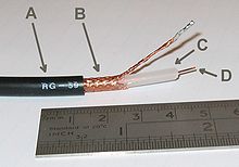
Transmission medium
A transmission medium (plural transmission media) is a material substance (solid, liquid, gas, or plasma) that can propagate energy waves. For example, the transmission medium for sound received by the ears is usually air, but solids and liquids may also act as transmission media for sound.
The absence of a material medium (the vacuum of empty space) can also be thought of as a transmission medium for electromagnetic waves such as light and radio waves. While material substance is not required for electromagnetic waves to propagate, such waves are usually affected by the transmission media they pass through, for instance by absorption or by reflection or refraction at the interfaces between media.
The term transmission medium can also refer to a technical device that employs the material substance to transmit or guide waves. Thus, an optical fiber or a copper cable is referred to as a transmission medium.
A transmission medium can be classified as a:
 Electromagnetic radiation can be transmitted through an optical media, such as optical fiber, or through twisted pair wires, coaxial cable, or dielectric-slab waveguides. It may also pass through any physical material that is transparent to the specific wavelength, such as water, air, glass, or concrete. Sound is, by definition, the vibration of matter, so it requires a physical medium for transmission, as does other kinds of mechanical waves and heat energy. Historically, science incorporated various aether theories to explain the transmission medium. However, it is now known that electromagnetic waves do not require a physical transmission medium, and so can travel through the "vacuum" of free space. Regions of the insulative vacuum can become conductive for electrical conduction through the presence of free electrons, holes, or ions.
The absence of a material medium (the vacuum of empty space) can also be thought of as a transmission medium for electromagnetic waves such as light and radio waves. While material substance is not required for electromagnetic waves to propagate, such waves are usually affected by the transmission media they pass through, for instance by absorption or by reflection or refraction at the interfaces between media.
The term transmission medium can also refer to a technical device that employs the material substance to transmit or guide waves. Thus, an optical fiber or a copper cable is referred to as a transmission medium.
A transmission medium can be classified as a:
- Linear medium, if different waves at any particular point in the medium can be superposed;
- Bounded medium, if it is finite in extent, otherwise unbounded medium;
- Uniform medium or homogeneous medium, if its physical properties are unchanged at different points;
- Isotropic medium, if its physical properties are the same in different directions.

Coaxial Cable, one example of a transmission medium
Wednesday, June 8, 2011
Views of networks
Users and network administrators typically have different views of their networks. Users can share printers and some servers from a workgroup, which usually means they are in the same geographic location and are on the same LAN, whereas a Network Administrator is responsible to keep that network up and running. A community of interest has less of a connection of being in a local area, and should be thought of as a set of arbitrarily located users who share a set of servers , and possibly also communicate via peer-to-peer technologies.
Network administrators can see networks from both physical and logical perspectives. The physical perspective involves geographic locations, physical cabling, and the network elements (e.g., routers, bridges and application layer gateways that interconnect the physical media. Logical networks, called, in the TCP/IP architecture, subnets, map onto one or more physical media. For example, a common practice in a campus of buildings is to make a set of LAN cables in each building appear to be a common subnet, using virtual LAN (VLAN) technology.
Both users and administrators will be aware, to varying extents, of the trust and scope characteristics of a network. Again using TCP/IP architectural terminology, an intranet is a community of interest under private administration usually by an enterprise, and is only accessible by authorized users (e.g. employees).[15] Intranets do not have to be connected to the Internet, but generally have a limited connection. An extranet is an extension of an intranet that allows secure communications to users outside of the intranet (e.g. business partners, customers).[15]
Unofficially, the Internet is the set of users, enterprises, and content providers that are interconnected by Internet Service Providers (ISP). From an engineering viewpoint, the Internet is the set of subnets, and aggregates of subnets, which share the registered IP address space and exchange information about the reachability of those IP addresses using the Border Gateway Protocol. Typically, the human-readable names of servers are translated to IP addresses, transparently to users, via the directory function of the Domain Name System (DNS).
Over the Internet, there can be business-to-business (B2B), business-to-consumer (B2C) and consumer-to-consumer (C2C) communications. Especially when money or sensitive information is exchanged, the communications are apt to be secured by some form of communications security mechanism. Intranets and extranets can be securely superimposed onto the Internet, without any access by general Internet users and administrators, using secure Virtual Private Network (VPN) technology.
Firewalls
Firewalls are the most important aspect of a network with respect to security. A firewalled system does not need every interaction or data transfer monitored by a human, as automated processes can be set up to assist in rejecting access requests from unsafe sources, and allowing actions from recognized ones. The vital role firewalls play in network security grows in parallel with the constant increase in 'cyber' attacks for the purpose of stealing/corrupting data, planting viruses, etc.
Routers
A router is an internetworking device that forwards packets between networks by processing information found in the datagram or packet (Internet protocol information from Layer 3 of the OSI Model). In many situations, this information is processed in conjunction with the routing table (also known as forwarding table). Routers use routing tables to determine what interface to forward packets (this can include the "null" also known as the "black hole" interface because data can go into it, however, no further processing is done for said data).
Home
Home
Switches
A network switch is a device that forwards and filters OSI layer 2 datagrams (chunks of data communication) between ports (connected cables) based on the MAC addresses in the packets.[13] A switch is distinct from a hub in that it only forwards the frames to the ports involved in the communication rather than all ports connected. A switch breaks the collision domain but represents itself as a broadcast domain. Switches make forwarding decisions of frames on the basis of MAC addresses. A switch normally has numerous ports, facilitating a star topology for devices, and cascading additional switches.[14] Some switches are capable of routing based on Layer 3 addressing or additional logical levels; these are called multi-layer switches. The term switch is used loosely in marketing to encompass devices including routers and bridges, as well as devices that may distribute traffic on load or by application content (e.g., a Web URL identifier).home
Bridges
A network bridge connects multiple network segments at the data link layer (layer 2) of the OSI model. Bridges broadcast to all ports except the port on which the broadcast was received. However, bridges do not promiscuously copy traffic to all ports, as hubs do, but learn which MAC addresses are reachable through specific ports. Once the bridge associates a port and an address, it will send traffic for that address to that port only.
Bridges learn the association of ports and addresses by examining the source address of frames that it sees on various ports. Once a frame arrives through a port, its source address is stored and the bridge assumes that MAC address is associated with that port. The first time that a previously unknown destination address is seen, the bridge will forward the frame to all ports other than the one on which the frame arrived.
Bridges come in three basic types:
- Local bridges: Directly connect local area networks (LANs)
- Remote bridges: Can be used to create a wide area network (WAN) link between LANs. Remote bridges, where the connecting link is slower than the end networks, largely have been replaced with routers.
- Wireless bridges: Can be used to join LANs or connect remote stations to LANs.
Repeaters
A repeater is an electronic device that receives a signal, cleans it of unnecessary noise, regenerates it, and retransmits it at a higher power level, or to the other side of an obstruction, so that the signal can cover longer distances without degradation. In most twisted pair Ethernet configurations, repeaters are required for cable that runs longer than 100 meters. A repeater with multiple ports is known as a hub. Repeaters work on the Physical Layer of the OSI model. Repeaters require a small amount of time to regenerate the signal. This can cause a propagation delay which can affect network communication when there are several repeaters in a row. Many network architectures limit the number of repeaters that can be used in a row (e.g. Ethernet 5-4-3 rule).
Network classifications
Networks can be classified and named by their physical extent, and intended purpose. Common types of computer networks are outlined below.
 All interconnected devices must understand the network layer (layer 3), because they are handling multiple subnets (the different colors). Those inside the library, which have only 10/100 Mbit/s Ethernet connections to the user device and a Gigabit Ethernet connection to the central router, could be called "layer 3 switches" because they only have Ethernet interfaces and must understand IP. It would be more correct to call them access routers, where the router at the top is a distribution router that connects to the Internet and academic networks' customer access routers.

The defining characteristics of LANs, in contrast to WANs (Wide Area Networks), include their higher data transfer rates, smaller geographic range, and no need for leased telecommunication lines. Current Ethernet or other IEEE 802.3 LAN technologies operate at speeds up to 10 Gbit/s. This is the data transfer rate. IEEE has projects investigating the standardization of 40 and 100 Gbit/s.
Participants in the Internet use a diverse array of methods of several hundred documented, and often standardized, protocols compatible with the Internet Protocol Suite and an addressing system (IP addresses) administered by the Internet Assigned Numbers Authority and address registries. Service providers and large enterprises exchange information about the reachability of their address spaces through the Border Gateway Protocol (BGP), forming a redundant worldwide mesh of transmission paths.
An intranet is a set of networks, using the Internet Protocol and IP-based tools such as web browsers and file transfer applications, that is under the control of a single administrative entity. That administrative entity closes the intranet to all but specific, authorized users. Most commonly, an intranet is the internal network of an organization. A large intranet will typically have at least one web server to provide users with organizational information.
An extranet is a network that is limited in scope to a single organization or entity and also has limited connections to the networks of one or more other usually, but not necessarily, trusted organizations or entities—a company's customers may be given access to some part of its intranet—while at the same time the customers may not be considered trusted from a security standpoint. Technically, an extranet may also be categorized as a CAN, MAN, WAN, or other type of network, although an extranet cannot consist of a single LAN; it must have at least one connection with an external network.
.
Home
Local area network
A local area network (LAN) is a network that connects computers and devices in a limited geographical area such as home, school, computer laboratory, office building, or closely positioned group of buildings. Each computer or device on the network is a node. Current wired LANs are most likely to be based on Ethernet technology, although new standards like ITU-T G.hn also provide a way to create a wired LAN using existing home wires (coaxial cables, phone lines and power lines).
Wide area network
A wide area network (WAN) is a computer network that covers a large geographic area such as a city, country, or spans even intercontinental distances, using a communications channel that combines many types of media such as telephone lines, cables, and air waves. A WAN often uses transmission facilities provided by common carriers, such as telephone companies. WAN technologies generally function at the lower three layers of the OSI reference model: the physical layer, the data link layer, and the network layerInternet
The Internet is a global system of interconnected governmental, academic, corporate, public, and private computer networks. It is based on the networking technologies of the Internet Protocol Suite. It is the successor of the Advanced Research Projects Agency Network (ARPANET) developed by DARPA of the United States Department of Defense. The Internet is also the communications backbone underlying the World Wide Web (WWW).Participants in the Internet use a diverse array of methods of several hundred documented, and often standardized, protocols compatible with the Internet Protocol Suite and an addressing system (IP addresses) administered by the Internet Assigned Numbers Authority and address registries. Service providers and large enterprises exchange information about the reachability of their address spaces through the Border Gateway Protocol (BGP), forming a redundant worldwide mesh of transmission paths.
Intranets and extranets
Intranets and extranets are parts or extensions of a computer network, usually a local area network.An intranet is a set of networks, using the Internet Protocol and IP-based tools such as web browsers and file transfer applications, that is under the control of a single administrative entity. That administrative entity closes the intranet to all but specific, authorized users. Most commonly, an intranet is the internal network of an organization. A large intranet will typically have at least one web server to provide users with organizational information.
An extranet is a network that is limited in scope to a single organization or entity and also has limited connections to the networks of one or more other usually, but not necessarily, trusted organizations or entities—a company's customers may be given access to some part of its intranet—while at the same time the customers may not be considered trusted from a security standpoint. Technically, an extranet may also be categorized as a CAN, MAN, WAN, or other type of network, although an extranet cannot consist of a single LAN; it must have at least one connection with an external network.
.
Home
Network topology
Network topology is the layout pattern of interconnections of the various elements (links, nodes, etc.) of a computer or biological network.Network topologies may be physical or logical. Physical topology refers to the the physical design of a network including the devices, location and cable installation. Logical topology refers to how data is actually transferred in a network as opposed to its physical design. In general physical topology relates to a core network whereas logical topology relates to basic network.
Topology can be understood as the shape or structure of a network. This shape does not necessarily correspond to the actual physical design of the devices on the computer network. The computers on a home network can be arranged in a circle but it does not necessarily mean that it represents a ring topology.
Any particular network topology is determined only by the graphical mapping of the configuration of physical and/or logical connections between nodes. The study of network topology uses graph theory. Distances between nodes, physical interconnections, transmission rates, and/or signal types may differ in two networks and yet their topologies may be identical.
A local area network (LAN) is one example of a network that exhibits both a physical topology and a logical topology. Any given node in the LAN has one or more links to one or more nodes in the network and the mapping of these links and nodes in a graph results in a geometric shape that may be used to describe the physical topology of the network. Likewise, the mapping of the data flow between the nodes in the network determines the logical topology of the network. The physical and logical topologies may or may not be identical in any particular network.


 The number of connections in a full mesh = n(n - 1) / 2.

Topology can be understood as the shape or structure of a network. This shape does not necessarily correspond to the actual physical design of the devices on the computer network. The computers on a home network can be arranged in a circle but it does not necessarily mean that it represents a ring topology.
Any particular network topology is determined only by the graphical mapping of the configuration of physical and/or logical connections between nodes. The study of network topology uses graph theory. Distances between nodes, physical interconnections, transmission rates, and/or signal types may differ in two networks and yet their topologies may be identical.
A local area network (LAN) is one example of a network that exhibits both a physical topology and a logical topology. Any given node in the LAN has one or more links to one or more nodes in the network and the mapping of these links and nodes in a graph results in a geometric shape that may be used to describe the physical topology of the network. Likewise, the mapping of the data flow between the nodes in the network determines the logical topology of the network. The physical and logical topologies may or may not be identical in any particular network.

1.Bus

- In local area networks where bus topology is used, each node is connected to a single cable. Each computer or server is connected to the single bus cable. A signal from the source travels in both directions to all machines connected on the bus cable until it finds the intended recipient. If the machine address does not match the intended address for the data, the machine ignores the data. Alternatively, if the data does match the machine address, the data is accepted. Since the bus topology consists of only one wire, it is rather inexpensive to implement when compared to other topologies. However, the low cost of implementing the technology is offset by the high cost of managing the network. Additionally, since only one cable is utilized, it can be the single point of failure. If the network cable breaks, the entire network will be down.
2.Star
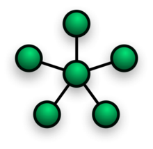 Star network topology
 - In local area networks with a star topology, each network host is connected to a central hub with a point-to-point connection. All traffic that traverses the network passes through the central hub. The hub acts as a signal repeater. The star topology is considered the easiest topology to design and implement. An advantage of the star topology is the simplicity of adding additional nodes. The primary disadvantage of the star topology is that the hub represents a single point of failure.

- Notes
- A point-to-point link (described above) is sometimes categorized as a special instance of the physical star topology – therefore, the simplest type of network that is based upon the physical star topology would consist of one node with a single point-to-point link to a second node, the choice of which node is the 'hub' and which node is the 'spoke' being arbitrary.
- After the special case of the point-to-point link, as in note (1) above, the next simplest type of network that is based upon the physical star topology would consist of one central node – the 'hub' – with two separate point-to-point links to two peripheral nodes – the 'spokes'.
- Although most networks that are based upon the physical star topology are commonly implemented using a special device such as a hub or switch as the central node (i.e., the 'hub' of the star), it is also possible to implement a network that is based upon the physical star topology using a computer or even a simple common connection point as the 'hub' or central node.
- Star networks may also be described as either broadcast multi-access or nonbroadcast multi-access (NBMA), depending on whether the technology of the network either automatically propagates a signal at the hub to all spokes, or only addresses individual spokes with each communication.
3.Ring
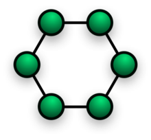 Ring network topology
- A network topology that is set up in a circular fashion in which data travels around the ring in one direction and each device on the right acts as a repeater to keep the signal strong as it travels. Each device incorporates a receiver for the incoming signal and a transmitter to send the data on to the next device in the ring. The network is dependent on the ability of the signal to travel around the ring.
3.Mesh
Main article: Mesh networkingThe value of fully meshed networks is proportional to the exponent of the number of subscribers, assuming that communicating groups of any two endpoints, up to and including all the endpoints, is approximated by Reed's Law.
- Fully connected


-
- Note: The physical fully connected mesh topology is generally too costly and complex for practical networks, although the topology is used when there are only a small number of nodes to be interconnected.
- Partially connected

Partially connected mesh topology
-
- The type of network topology in which some of the nodes of the network are connected to more than one other node in the network with a point-to-point link – this makes it possible to take advantage of some of the redundancy that is provided by a physical fully connected mesh topology without the expense and complexity required for a connection between every node in the network.
-
- Note: In most practical networks that are based upon the partially connected mesh topology, all of the data that is transmitted between nodes in the network takes the shortest path between nodes, except in the case of a failure or break in one of the links, in which case the data takes an alternative path to the destination. This requires that the nodes of the network possess some type of logical 'routing' algorithm to determine the correct path to use at any particular time.
4.Tree

The type of network topology in which a central 'root' node (the top level of the hierarchy) is connected to one or more other nodes that are one level lower in the hierarchy (i.e., the second level) with a point-to-point link between each of the second level nodes and the top level central 'root' node, while each of the second level nodes that are connected to the top level central 'root' node will also have one or more other nodes that are one level lower in the hierarchy (i.e., the third level) connected to it, also with a point-to-point link, the top level central 'root' node being the only node that has no other node above it in the hierarchy (The hierarchy of the tree is symmetrical.) Each node in the network having a specific fixed number, of nodes connected to it at the next lower level in the hierarchy, the number, being referred to as the 'branching factor' of the hierarchical tree.This tree has individual peripheral nodes.
-
- A network that is based upon the physical hierarchical topology must have at least three levels in the hierarchy of the tree, since a network with a central 'root' node and only one hierarchical level below it would exhibit the physical topology of a star.
- A network that is based upon the physical hierarchical topology and with a branching factor of 1 would be classified as a physical linear topology.
- The branching factor, f, is independent of the total number of nodes in the network and, therefore, if the nodes in the network require ports for connection to other nodes the total number of ports per node may be kept low even though the total number of nodes is large – this makes the effect of the cost of adding ports to each node totally dependent upon the branching factor and may therefore be kept as low as required without any effect upon the total number of nodes that are possible.
- The total number of point-to-point links in a network that is based upon the physical hierarchical topology will be one less than the total number of nodes in the network.
- If the nodes in a network that is based upon the physical hierarchical topology are required to perform any processing upon the data that is transmitted between nodes in the network, the nodes that are at higher levels in the hierarchy will be required to perform more processing operations on behalf of other nodes than the nodes that are lower in the hierarchy. Such a type of network topology is very useful and highly recommended.
-
5.Hybrid
Hybrid networks use a combination of any two or more topologies in such a way that the resulting network does not exhibit one of the standard topologies (e.g., bus, star, ring, etc.). For example, a tree network connected to a tree network is still a tree network topology. A hybrid topology is always produced when two different basic network topologies are connected. Two common examples for Hybrid network are: star ring network and star bus network- A Star ring network consists of two or more star topologies connected using a multistation access unit (MAU) as a centralized hub.
- A Star Bus network consists of two or more star topologies connected using a bus trunk (the bus trunk serves as the network's backbone).
6.Daisy chain
Except for star-based networks, the easiest way to add more computers into a network is by daisy-chaining, or connecting each computer in series to the next. If a message is intended for a computer partway down the line, each system bounces it along in sequence until it reaches the destination. A daisy-chained network can take two basic forms: linear and ring.- A linear topology puts a two-way link between one computer and the next. However, this was expensive in the early days of computing, since each computer (except for the ones at each end) required two receivers and two transmitters.
- By connecting the computers at each end, a ring topology can be formed. An advantage of the ring is that the number of transmitters and receivers can be cut in half, since a message will eventually loop all of the way around. When a node sends a message, the message is processed by each computer in the ring. If a computer is not the destination node, it will pass the message to the next node, until the message arrives at its destination. If the message is not accepted by any node on the network, it will travel around the entire ring and return to the sender. This potentially results in a doubling of travel time for data.

- Note: In most practical networks that are based upon the partially connected mesh topology, all of the data that is transmitted between nodes in the network takes the shortest path between nodes, except in the case of a failure or break in one of the links, in which case the data takes an alternative path to the destination. This requires that the nodes of the network possess some type of logical 'routing' algorithm to determine the correct path to use at any particular time.


Networking
A computer network, often simply referred to as a network, is a collection of computers and devices interconnected by communications channels that facilitate communications and allows sharing of resources and information among interconnected devices.Computer networking or Data communications (Datacom) is the engineering discipline concerned with the computer networks. Computer networking is sometimes considered a sub-discipline of electrical engineering, telecommunications, computer science, information technology and/or computer engineering since it relies heavily upon the theoretical and practical application of these scientific and engineering disciplines.
The three types of networks are: the Internet, the intranet, and the extranet. Examples of different network methods are:

Networks may be classified according to a wide variety of characteristics such as topology, connection method and scale.
All networks are interconnected to allow communication with a variety of different kinds of media, including twisted-pair copper wire cable, coaxial cable, optical fiber, power lines and various wireless technologies.The devices can be separated by a few meters (e.g. via Bluetooth) or nearly unlimited distances (e.g. via the interconnections of the Internet). Networking, routers, routing protocols, and networking over the public Internet have their specifications defined in documents called RFCs.

Computer networks can be used for a variety of purposes:
The three types of networks are: the Internet, the intranet, and the extranet. Examples of different network methods are:
- Local area network (LAN), which is usually a small network constrained to a small geographic area. An example of a LAN would be a computer network within a building.
- Metropolitan area network (MAN), which is used for medium size area. examples for a city or a state.
- Wide area network (WAN) that is usually a larger network that covers a large geographic area.
- Wireless LANs and WANs (WLAN & WWAN) are the wireless equivalent of the LAN and WAN.

Networks may be classified according to a wide variety of characteristics such as topology, connection method and scale.
All networks are interconnected to allow communication with a variety of different kinds of media, including twisted-pair copper wire cable, coaxial cable, optical fiber, power lines and various wireless technologies.The devices can be separated by a few meters (e.g. via Bluetooth) or nearly unlimited distances (e.g. via the interconnections of the Internet). Networking, routers, routing protocols, and networking over the public Internet have their specifications defined in documents called RFCs.

Computer networks can be used for a variety of purposes:
- Facilitating communications
- Using a network, people can communicate efficiently and easily via email, instant messaging, chat rooms, telephone, video telephone calls, and video conferencing.
- Sharing hardware
- In a networked environment, each computer on a network may access and use hardware resources on the network, such as printing a document on a shared network printer.
- Sharing files, data, and information
- In a network environment, authorized user may access data and information stored on other computers on the network. The capability of providing access to data and information on shared storage devices is an important feature of many networks.
- Sharing software
- Users connected to a network may run application programs on remote computers.
Connection method
Computer networks can be classified according to the hardware and software technology that is used to interconnect the individual devices in the network, such as optical fiber, Ethernet, wireless LAN, HomePNA, power line communication or G.hn. Ethernet as it is defined by IEEE 802 utilizes various standards and mediums that enable communication between devices. Frequently deployed devices include hubs, switches, bridges, or routers. Wireless LAN technology is designed to connect devices without wiring. These devices use radio waves or infrared signals as a transmission medium. ITU-T G.hn technology uses existing home wiring (coaxial cable, phone lines and power lines) to create a high-speed (up to 1 Gigabit/s) local area network.
Subscribe to:
Posts (Atom)