Topology can be understood as the shape or structure of a network. This shape does not necessarily correspond to the actual physical design of the devices on the computer network. The computers on a home network can be arranged in a circle but it does not necessarily mean that it represents a ring topology.
Any particular network topology is determined only by the graphical mapping of the configuration of physical and/or logical connections between nodes. The study of network topology uses graph theory. Distances between nodes, physical interconnections, transmission rates, and/or signal types may differ in two networks and yet their topologies may be identical.
A local area network (LAN) is one example of a network that exhibits both a physical topology and a logical topology. Any given node in the LAN has one or more links to one or more nodes in the network and the mapping of these links and nodes in a graph results in a geometric shape that may be used to describe the physical topology of the network. Likewise, the mapping of the data flow between the nodes in the network determines the logical topology of the network. The physical and logical topologies may or may not be identical in any particular network.

1.Bus

- In local area networks where bus topology is used, each node is connected to a single cable. Each computer or server is connected to the single bus cable. A signal from the source travels in both directions to all machines connected on the bus cable until it finds the intended recipient. If the machine address does not match the intended address for the data, the machine ignores the data. Alternatively, if the data does match the machine address, the data is accepted. Since the bus topology consists of only one wire, it is rather inexpensive to implement when compared to other topologies. However, the low cost of implementing the technology is offset by the high cost of managing the network. Additionally, since only one cable is utilized, it can be the single point of failure. If the network cable breaks, the entire network will be down.
2.Star
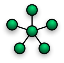 Star network topology
 - In local area networks with a star topology, each network host is connected to a central hub with a point-to-point connection. All traffic that traverses the network passes through the central hub. The hub acts as a signal repeater. The star topology is considered the easiest topology to design and implement. An advantage of the star topology is the simplicity of adding additional nodes. The primary disadvantage of the star topology is that the hub represents a single point of failure.

- Notes
- A point-to-point link (described above) is sometimes categorized as a special instance of the physical star topology – therefore, the simplest type of network that is based upon the physical star topology would consist of one node with a single point-to-point link to a second node, the choice of which node is the 'hub' and which node is the 'spoke' being arbitrary.
- After the special case of the point-to-point link, as in note (1) above, the next simplest type of network that is based upon the physical star topology would consist of one central node – the 'hub' – with two separate point-to-point links to two peripheral nodes – the 'spokes'.
- Although most networks that are based upon the physical star topology are commonly implemented using a special device such as a hub or switch as the central node (i.e., the 'hub' of the star), it is also possible to implement a network that is based upon the physical star topology using a computer or even a simple common connection point as the 'hub' or central node.
- Star networks may also be described as either broadcast multi-access or nonbroadcast multi-access (NBMA), depending on whether the technology of the network either automatically propagates a signal at the hub to all spokes, or only addresses individual spokes with each communication.
3.Ring
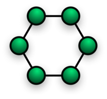 Ring network topology
- A network topology that is set up in a circular fashion in which data travels around the ring in one direction and each device on the right acts as a repeater to keep the signal strong as it travels. Each device incorporates a receiver for the incoming signal and a transmitter to send the data on to the next device in the ring. The network is dependent on the ability of the signal to travel around the ring.
3.Mesh
Main article: Mesh networkingThe value of fully meshed networks is proportional to the exponent of the number of subscribers, assuming that communicating groups of any two endpoints, up to and including all the endpoints, is approximated by Reed's Law.
- Fully connected


-
- Note: The physical fully connected mesh topology is generally too costly and complex for practical networks, although the topology is used when there are only a small number of nodes to be interconnected.
- Partially connected

Partially connected mesh topology
-
- The type of network topology in which some of the nodes of the network are connected to more than one other node in the network with a point-to-point link – this makes it possible to take advantage of some of the redundancy that is provided by a physical fully connected mesh topology without the expense and complexity required for a connection between every node in the network.
-
- Note: In most practical networks that are based upon the partially connected mesh topology, all of the data that is transmitted between nodes in the network takes the shortest path between nodes, except in the case of a failure or break in one of the links, in which case the data takes an alternative path to the destination. This requires that the nodes of the network possess some type of logical 'routing' algorithm to determine the correct path to use at any particular time.
4.Tree

The type of network topology in which a central 'root' node (the top level of the hierarchy) is connected to one or more other nodes that are one level lower in the hierarchy (i.e., the second level) with a point-to-point link between each of the second level nodes and the top level central 'root' node, while each of the second level nodes that are connected to the top level central 'root' node will also have one or more other nodes that are one level lower in the hierarchy (i.e., the third level) connected to it, also with a point-to-point link, the top level central 'root' node being the only node that has no other node above it in the hierarchy (The hierarchy of the tree is symmetrical.) Each node in the network having a specific fixed number, of nodes connected to it at the next lower level in the hierarchy, the number, being referred to as the 'branching factor' of the hierarchical tree.This tree has individual peripheral nodes.
-
- A network that is based upon the physical hierarchical topology must have at least three levels in the hierarchy of the tree, since a network with a central 'root' node and only one hierarchical level below it would exhibit the physical topology of a star.
- A network that is based upon the physical hierarchical topology and with a branching factor of 1 would be classified as a physical linear topology.
- The branching factor, f, is independent of the total number of nodes in the network and, therefore, if the nodes in the network require ports for connection to other nodes the total number of ports per node may be kept low even though the total number of nodes is large – this makes the effect of the cost of adding ports to each node totally dependent upon the branching factor and may therefore be kept as low as required without any effect upon the total number of nodes that are possible.
- The total number of point-to-point links in a network that is based upon the physical hierarchical topology will be one less than the total number of nodes in the network.
- If the nodes in a network that is based upon the physical hierarchical topology are required to perform any processing upon the data that is transmitted between nodes in the network, the nodes that are at higher levels in the hierarchy will be required to perform more processing operations on behalf of other nodes than the nodes that are lower in the hierarchy. Such a type of network topology is very useful and highly recommended.
-
5.Hybrid
Hybrid networks use a combination of any two or more topologies in such a way that the resulting network does not exhibit one of the standard topologies (e.g., bus, star, ring, etc.). For example, a tree network connected to a tree network is still a tree network topology. A hybrid topology is always produced when two different basic network topologies are connected. Two common examples for Hybrid network are: star ring network and star bus network- A Star ring network consists of two or more star topologies connected using a multistation access unit (MAU) as a centralized hub.
- A Star Bus network consists of two or more star topologies connected using a bus trunk (the bus trunk serves as the network's backbone).
6.Daisy chain
Except for star-based networks, the easiest way to add more computers into a network is by daisy-chaining, or connecting each computer in series to the next. If a message is intended for a computer partway down the line, each system bounces it along in sequence until it reaches the destination. A daisy-chained network can take two basic forms: linear and ring.- A linear topology puts a two-way link between one computer and the next. However, this was expensive in the early days of computing, since each computer (except for the ones at each end) required two receivers and two transmitters.
- By connecting the computers at each end, a ring topology can be formed. An advantage of the ring is that the number of transmitters and receivers can be cut in half, since a message will eventually loop all of the way around. When a node sends a message, the message is processed by each computer in the ring. If a computer is not the destination node, it will pass the message to the next node, until the message arrives at its destination. If the message is not accepted by any node on the network, it will travel around the entire ring and return to the sender. This potentially results in a doubling of travel time for data.

- Note: In most practical networks that are based upon the partially connected mesh topology, all of the data that is transmitted between nodes in the network takes the shortest path between nodes, except in the case of a failure or break in one of the links, in which case the data takes an alternative path to the destination. This requires that the nodes of the network possess some type of logical 'routing' algorithm to determine the correct path to use at any particular time.


No comments:
Post a Comment